SLA Micro-Fluidic Device
Microfluidic Devices: An Introduction
Microfluidic devices are designed to process fluids, likely containing small particles, cells, or other reagents, at a micro scale. In form, these devices consist of small channels designed in such a way that a specific task is completed, like:
- Mixing small quantities of expensive reagents,
- Testing new pharmaceutical drugs on organs-on-a-chip, and
- Sorting specific cells from blood
Many of the most traditional applications exist within the domain of biology and medicine.
What does this Microfluidic device do and why?
Mix!
In this project, a microfluidic mixer was designed. While perhaps not immediately applicable to Computer Science, it is easy to imagine such devices being used in the field in the future. As rare and precious earth metals grow more expensive, it would be beneficial to create more efficient ways to form alloyed materials. Moreover, it becomes necessary to consider than new semi-conductor materials may be needed in the not-so-distant future. Microfluidics may provide a way to meet both challenges while leveraging a technology that is already established in other domains.
The Design
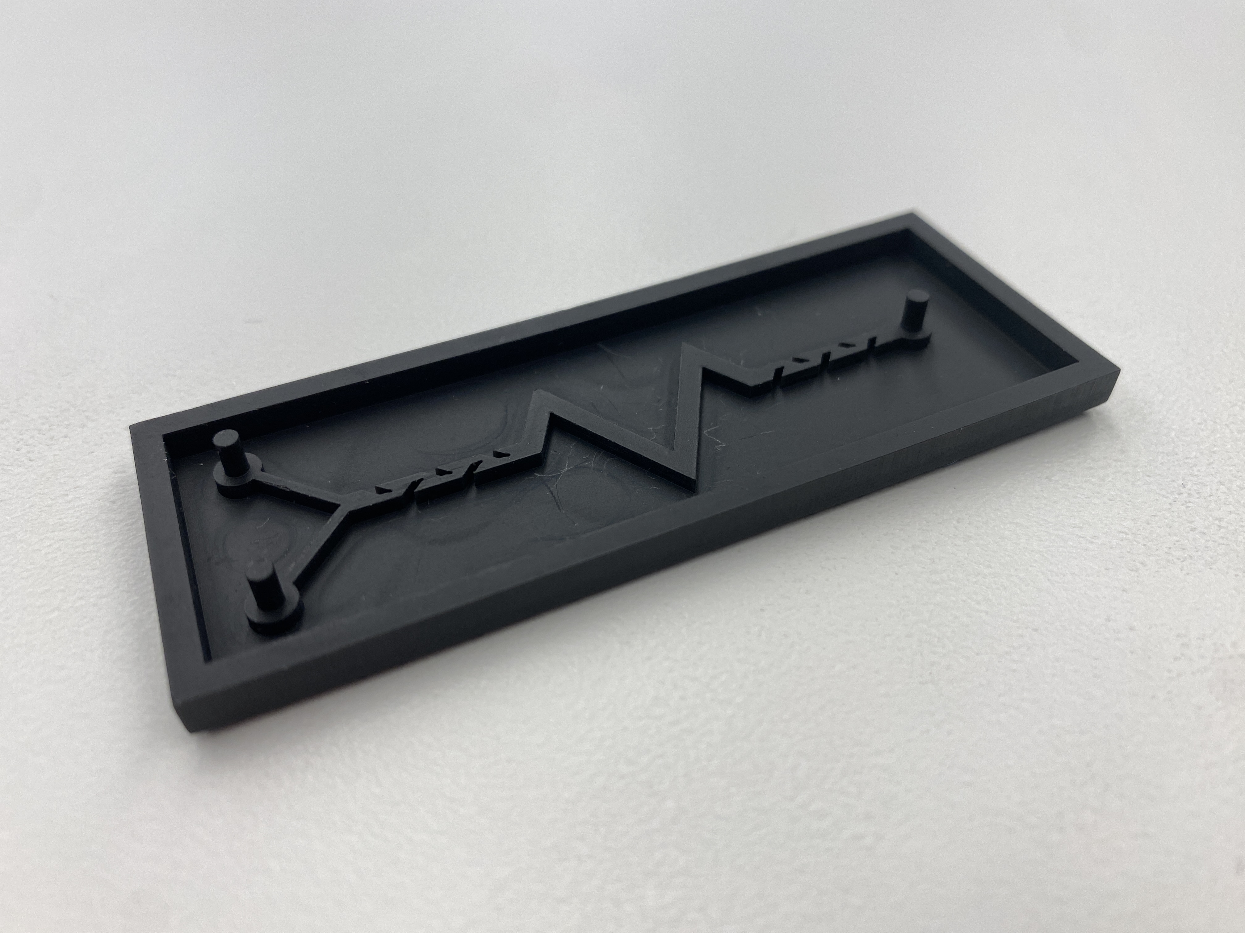
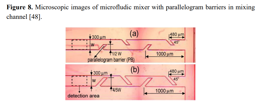
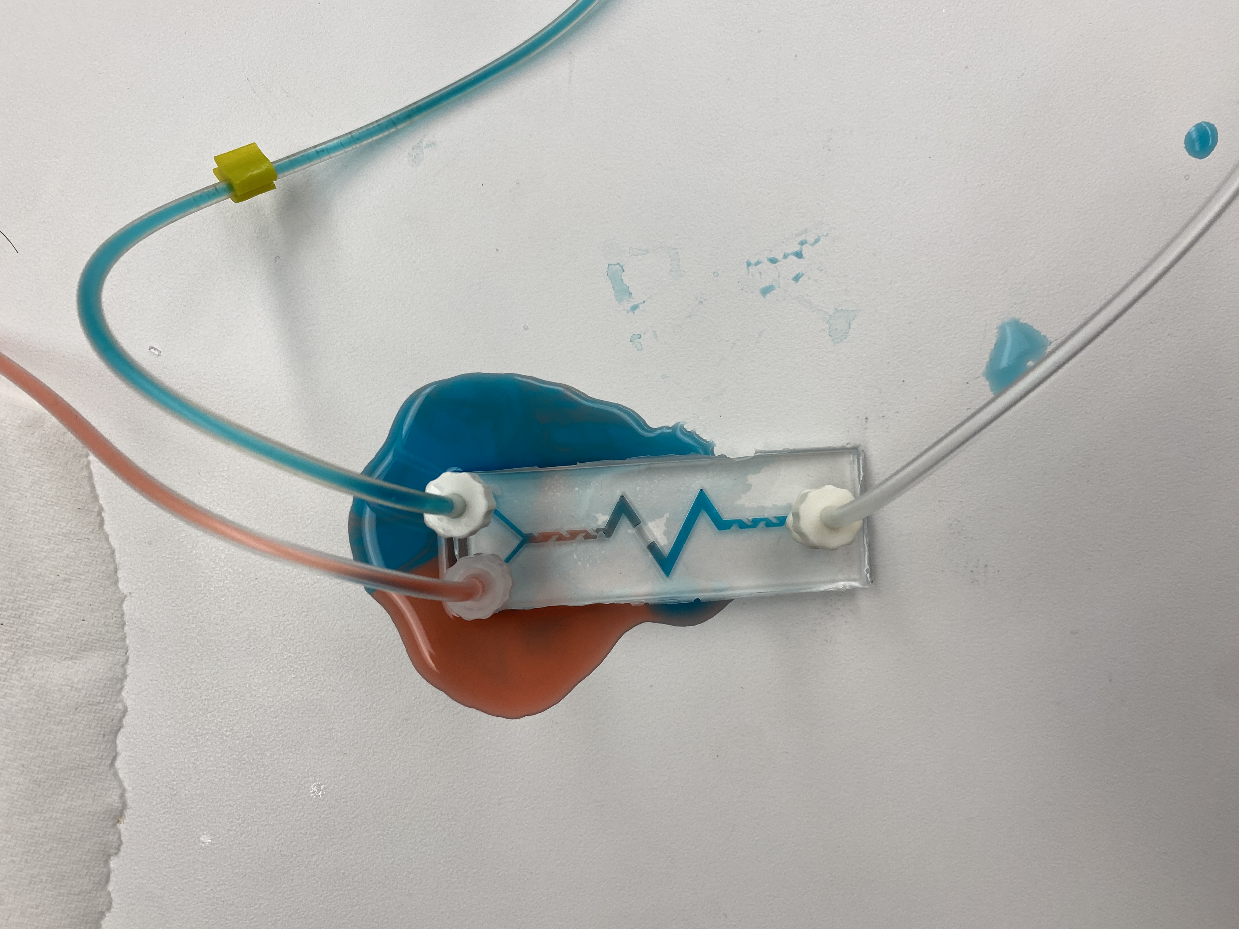
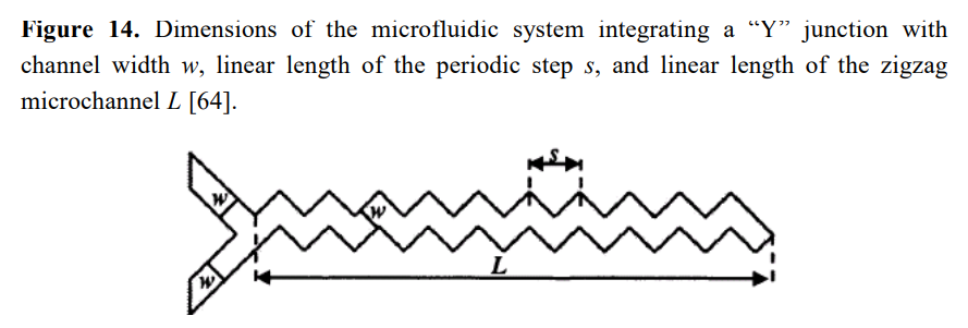
The device uses two different mixing patterns to efficiently mix the two fluids that enter. The design begins with two inlets that converge into one channel. The fluid will encounter five parallelogram barriers within the channel at the beginning and end of its duration with a zigzag pattern between. Due to the inherently laminar characteristics of the micro-scaled flows, mixing in passive micromixers relies predominantly on chaotic advection effects. Therefore, that was the thought process of the parallelogram barriers and the zigzag. Both techniques induce shear forces and inertial effects within the fluid as it interacts with another fluid.
More simply, the device is designed to heighten the diffusion effects between the different fluids in the channels by increasing the contact area and time of the two regents. This technique categorizes the devices as a “passive” mixer instead of an active one because no external energy or force is applied to agitate the fluids in the channels. Thus, the project contains no moving parts nor does it require any energy to be input apart from the flow pressure of the liquids.
Design Process
Without any prior experience designing microfluidics, the first step in creating this design was to review an existing paper, which provided an overview of the current field of microfluidic mixers and was titled: “Microfluidic Mixing: A Review”.
After reading the paper, a few of the designs stuck out as being well suited to mixing small quantities of reagents. A subset of those designs appeared like good candidates for the process that would be used to create the device. That is, while the Form 3 does have micrometer scale resolution, a feature which is very fine in the x-y dimension but tall in the z dimension would be unlikely to demold well after being molded into PDMS. Therefore, many of the designs with very small sub-channels were not the right choice for the project.
Ultimately, a combination of the two designs below were chosen and unified into a single device. (These images are courtesy of “Microfluidic Mixing: A Review” which is cited below.)
Initially, the small parallelogram insets within the channels were designed to be 0.5 mm thick and 2 mm deep. After printing a prototype of the mold on the SLA printer, it seemed unlikely that these features would demold properly. The width of the parallelograms was subsequently widened to 1 mm in order to increase the chance that the device would be able to be manufactured.
Manufactured Device
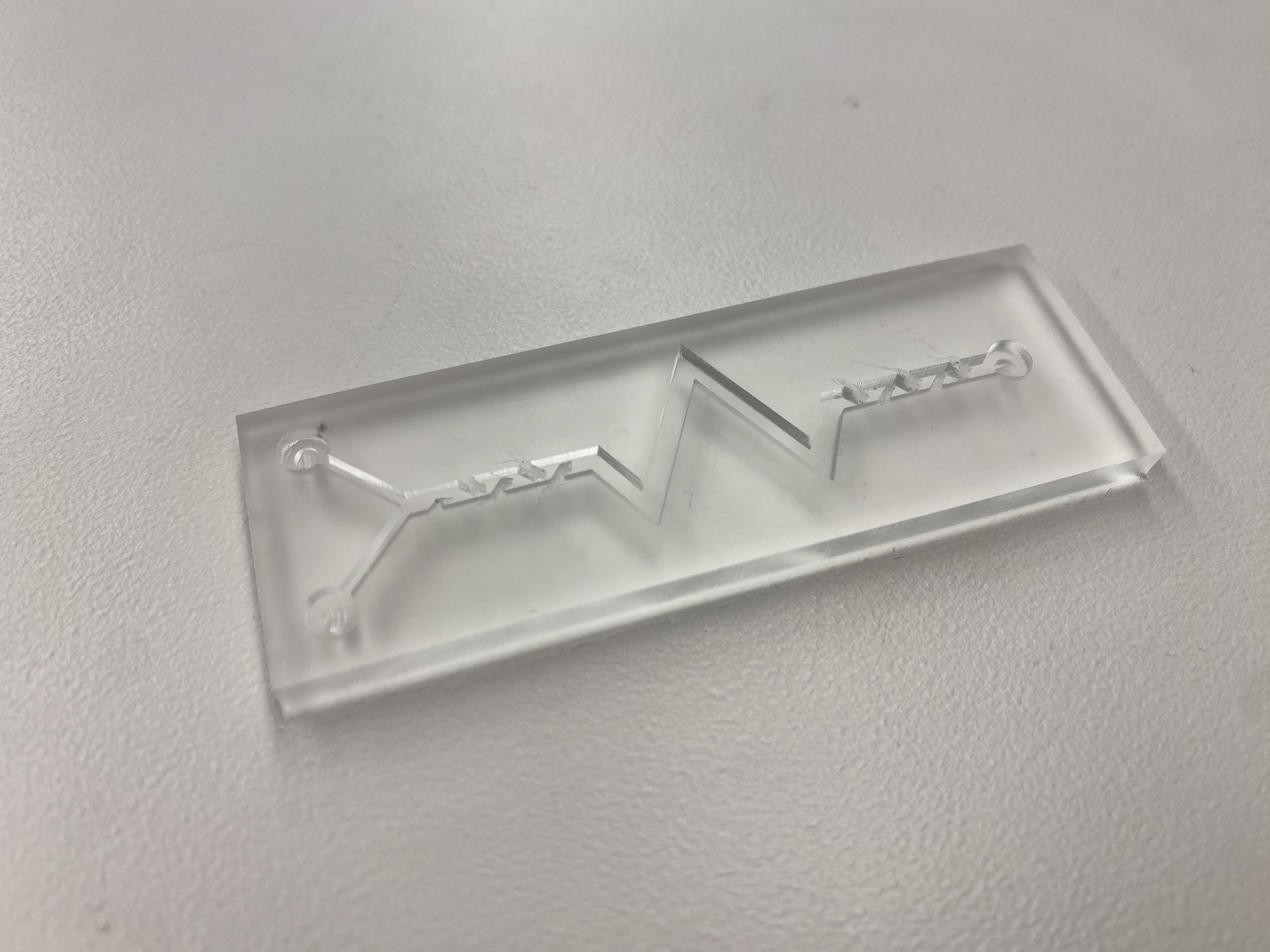
Why was VPP chosen to print the negative mold?
The FormLabs Form 3 SLA printer was used to 3D print the mold of the microfluidic device and there is a multitude of reasons why Stereolithography (SLA) or Vat photopolymerization (VPP) was selected to do so including:
- High Resolution/ Accuracy: VPP printers are capable of producing high-resolution parts with intricate details and a smooth surface finish. This makes SLA printing ideal for creating objects with fine details and complex geometries. The Form 3 specifically has an XY Resolution of 25 microns and a Laser Spot Size of 85 microns.
- Surface Finish: Another advantage of SLA printers is that they can work with a variety of materials, including various types of resins, which can offer different properties such as flexibility, toughness, or transparency. In this project, Black Resin was used based on availability and matte surface finish.
- Speed: SLA printing at a very high detail (.025 mm) can be faster than other 3D printing or additive manufacturing technologies, especially for smaller parts.
- Watertight: VPP parts are printed watertight create the actual device, the mold must be Parylened and must be smooth and watertight so that the mold can hold.
- Minimal post-processing: Due to the smooth finish, the only required post-processing included removing supports, washing the part, and minimal curing (material properties are not crucial in this case).
Due to this project’s specific use case, the available technology at hand and all of the benefits mentioned above, Stereolithography was the best candidate among 3D printing technologies with which to create the negative mold for the microfluidic device.
CAD Model of Device
Citations
Lee C-Y, Chang C-L, Wang Y-N, Fu L-M. Microfluidic Mixing: A Review. International Journal of Molecular Sciences. 2011; 12(5):3263-3287. https://doi.org/10.3390/ijms12053263
